 To build a canister, you will need the following parts. They are available at your local home improvement centers and auto parts stores.
This is page describes how to address the oil seepage from the PCV breather tube. This problem is more prevalent with turbocharged engines. Although it is possible to fix the baffle that is supposed to prevent seepage, it doesn't always eliminate the problem. Therefore, there is also a procedure to build a PCV breather oil canister. Its purpose is to sit between the PCV breather vent hose and the air box. It will catch the oil leaking out of the vent, while recirculating the gasses back into the engine as before. Modifying your PCV system may not be legal in some states, however no increase in emissions should results from the modification.
From mid-1987 onward, Chrysler decided that it wasn't necessary to properly install the crankcase breather baffle on the valve cover. This baffle was designed to allow crankcase gasses to escape while keeping the oil inside by running the gasses through a series of channels. Since the channels are not sealed against the valve cover properly, the oil bypasses them and exits out the breather vent into the PCV system. The net result is oil in your air box. You can either try to fix the baffle, or you can build an oil canisters to catch the oil before it gets to the filter.
It is possible to try to fix the baffle in the valve cover that is supposed to trap the oil before it can get out into the PCV system. There are a few problems with the design of it. Firstly, it is positioned low on the rear of the valve cover. Since the engine is tilted back slightly and the oil return for the valve train is at the front of the head, oil tends to pool back in the corners, especially during acceleration. This makes the baffle's job harder. The second problem is that the factory does not try to seal the channels of the baffle to the inside of the valve cover. Rather than get trapped by the baffles and drain out the bottom, the oil seeps through the gap between the channels and the valve cover. Finally, the PCV itself is forced shut when the turbocharged engines are in boost. The build-up of crankcase gasses creates a positive pressure which then flows out of the breather tube. Excessive blow-by in the cylinders (worn or broken piston rings) can cause excessive positive pressure to build up in the crankcase. The gasses then flow too fast through the baffle and it cannot remove the oil. In extreme cases of this, the oil dip stick will pop out of the tube and spray oil in the engine bay.
Below is the procedure to fix the baffle. Minimally, you will need a new valve cover gasket and a tube of Ultra Black RTV. You may also need to replace the rubber piece that connects the PCV and breather tube to the valve cover (usually called the "PCV grommet", even though it isn't really a grommet).
Even with a properly installed baffle, it is still possible to get excessive oil seepage from the PCV breather. This is more prevalent on high performance engines because of the increased boost levels and more spirited driving. This procedure build the canister out of PCV parts. Certainly it is possible to build it other ways, such as soldering brass tubing to a tin can, etc. This procedure should require the fewest number of special tools and skills.
To build a canister, you will need the following parts. They are available at your local home improvement centers and auto parts stores.
To install the canister, you will also need the following parts:
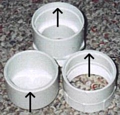
You can assemble the PCV female-pipe to female-threaded adapter to the pipe cap either by cementing them directly together, or by using a short piece of 2" PVC pipe to cement them. If you decide to just cement them together, I recommend sanding the mating surfaces flat by laying sandpaper on a flat board and sanding the surfaces flat. You can also use a lathe to cut notches into the mating surfaces so that they can get a better grip. Be sure you cement the right adapter to the pipe cap. The notches you'd make are shown in the two bottom pieces in the picture below:
For the third PCV part (the female pipe to male threaded pipe adapter), you will need to make a notch anyway. This is to fit the PCV breather filter can into the adapter. If you don't have access to a lathe, you could notch it out with a dremel, or melt the area by heating something that is the same diameter as the outside of the breather. I don't recommend heating the breather itself (unless you buy two of them), because you will probably melt the filter inside.
 The next step is to put the copper fitting reducer onto the breather canister. Be sure to buy the right part. This is NOT a 1" pipe to 3/4" pipe adapter. It is a 1" fitting to 3/4" pipe adapter. The difference is that the larger end on the fitting adapter is smaller than on the pipe adapter. This is because the fitting adapter's large end is the same diameter as a 1" pipe, whereas the pipe adapter's large end is designed to accept a 1" pipe. Once you have the right part, you will see that it is slightly too small to fit over the lip on the bottom hose connection of the breather. You can either press it on by clamping the adapter and breather in a vise and pressing it in, or you can cut the lip off with a pipe cutter or hack saw and RTV it in place. I pressed it on and used RTV to seal it in place. The whole reason for the pipe adapter is to ensure that any dripping oil drips down into the bottom of the canister and not over to the vent.
Speaking of the vent, it is time to put it into the female pipe to male threaded pipe adapter. Do this by drill a 5/8" hole in the side of it. The hole needs to be above the threaded area, but low enough to clear the canister. If your adapter is way too short to do this, then you got a CPVC adapter and not a Schedule 40 PVC adapter. Be sure to get the Schedule 40 version!
 Once you have the hole drilled, you can glue a short piece of 1/2" CPVC pipe into the hole. If you are going to cement a fitting right to it, a 3/4" piece is about right. You can also use about a 1 1/2" piece and have the exit point straight out. Since 1/2" CPVC pipe has a 5/8" outer diameter, it is perfect for 5/8" radiator or emissions hose. Or you can glue a 1/2" CPVC "street tee" fitting right into the hole if you have a tight spot. What you do with the vent depends on the amount of clearance you have and the direction that you want the exit to point. For my application, I cemented a 3/4" piece of 1/2" CPVC pipe into the hole for a 1/2" 45 degree elbow that will be cemented to it. The image to the left shows to two sections glued together. The vent pipe is pointing towards the right, rear.
The last thing to do is to mount the filter breather to the top section. Drill 3 or 4 small 1/8" holes through the PVC adapter and the lip of the breather. Apply RTV around the lip for a good seal and use 1/4" #6 sheet metal screws to hold the breather in place.
The final installation of the canister depends on your situation. A 2 1/2" muffler hanger works well for 2" PVC pipe fittings, and they are flexible. The stock PCV breather vent pipe on the engine is a good place to start when trying to figure out where to put the canister. You can cut the pipe so that it works better for you. The hose from the pipe to canister should be made of emissions hose, because rubber radiator hose breaks down over time, when exposed to engine oil. Though it can be tricky to find, emissions hose can be found in 19/32" ID, which is just slightly smaller than 5/8" radiator hose. If the canister is put together properly, no oil should escape the vent and regular 5/8" radiator hose can be used here.
If you intend to connect the canister vent back to the induction system somehow, the canister should be connected as intended. That is, the metal hose connection on top should be connected to the PCV breather pipe on the engine, while the PVC side connection should be the vent back to the induction system. If you are connecting the vent back to a stock air box, make sure you install the correct breather filter for your air box. This will help keep debris and condensation out of the canister.
The following is probably illegal in most states: If you are going to allow the canister to vent to the atmosphere, you have the option of connection the canister in the opposite way. This way, the gasses are vented through the top connection, and are filtered to prevent debris and condensation from entering the canister.
You will periodically have to remove the canister and drain the oil from it (once per year is usually sufficient, preferably in the spring). If you live in a cold climate, you will find a build up of nasty yellow sludge instead of dirty oil in the winter. This is from condensation of the moist crankcase gasses in the valve cover and PCV system mixing with the oil. It is normal, but just be sure to clean it out in the spring.
| Return to MiniMopar Resources |
Updated 11/11/2003.
Copyright © 1996-2003 Russ W. Knize.