Replacing The Head Gasket
[ Improved Designs | Thermostat Modification | Emergency Repair | Complete Repair ]
[ Head Bolt Tightening Sequence | A/C Bracket Bolt Sequence ]
Symptoms
Engine suddenly overheats, radiator hose or heater hose explodes, a bubbling sound from the radiator overflow tank (may be a bad radiator cap), large bubbles in or foaming of coolant in radiator while engine is running, loss of coolant with no apparent leak, or persistent white smoke coming from exhaust.
Causes
- The engine overheated causing the head to warp. The overheat may have been caused by any of the following. See the Mini-Mopar Troubleshooter to find out more.
- Failure of the radiator fan or radiator fan relay.
- Thermostat did not open.
- Low radiator fluid, fluid leak, and/or water pump failure.
- Headgasket blew for other reason, causing loss of fluid and overheat.
- The engine overboosted. See the fault code 36.
- Known head gasket problem or improper headgasket installation.
Description
One of the weak links in these engines is the tendency for the 2.2L and 2.5L engines to blow the head gasket. The event that finally blows the gasket can vary, but the flaw in the original gasket design is what makes the gasket a weak point. Here are the details of the problem:
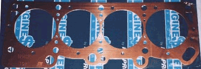
The surface area of the head and block near the corners is less than other areas. This is because there are more water jackets and oil passages in these areas, especially by cylinders #1 and #4. There is less surface area at the corners, so the gasket gets crushed because of too much pressure, which causes part of the gasket to "squirt" inside the cylinder, especially the back corner of #1. Too see this for yourself, take a pair of calipers or a micrometer, and measure the thickness of your used gasket at various places. Here is a picture of a gasket that I pulled out of my engine. It had not blown yet, but it was real close. The arrows point to where the gasket was crushed into the cylinder (sorry about the quality of the pic, I will get a better one soon):

The head bolt tightening sequence, according to Chrysler, has each bolt tightened to about 95 foot-pounds. Pressure equals Force divided by Area. The smaller the area (of the block and head) the larger the pressure (on the gasket) for the same amount of force (provided by the head bolt). With the gasket exposed inside the combustion chamber, the combustion "fire" burns the gasket away. Once the metal ring has been burned through, the fibrous part of the gasket quickly gives way and the gasket blows, usually into the corner water jacket by cylinder #1 or in between cylinders. In addition, the water pump is located close to cylinder #1. When the thermostat opens, colder coolant contacts the head on that side, which causes the head contract quicker than the block (since the head is aluminum and the block is steel). That is why the water passage by #1 is blocked by the gasket: to slow this effect. This expansion and contraction stresses the seal provided by the head gasket.
Improved Head Gasket Designs
Chrysler has superseded this old gasket design with a new, harder gasket that can withstand the increased pressure at the corners. Though new and untested by myself, this gasket is very similar to the original Fel-Pro gasket which had been used successfully by many. My measurements showed that the Fel-Pro gasket was slightly over-crushed at the corners, but did not deform or "squirt" into the cylinders. Unfortunately, The Fel-Pro gaskets were changed some time in the late 90s and now suffer from the same problems as the original. The new Mopar gaskets are made of a solid material instead of the fibrous material of the older style gasket. Victor-Reinz still makes the older gasket and I recommend avoiding it. As such, I can only recommend getting Mopar or Mopar Performance gasket. Fel-Pro does sell a 0.20" copper shim that can be used to drop your compression or to compensate for a milled head:
- 9296 SP - 0.020" head shim for non-cross-drilled head and block
The Mopar Performance headgasket is an even tougher design than the original Fel-Pro. Although it is designed for high performance use, it can be used on any stock engine. I also recommend going with the Mopar Performance head bolts when using this gasket. They are actually cheaper than the stock Mopar bolts. Avoid all aftermarket bolts. Here are the part numbers:
- P4452005 - non-cross-drilled head and block
- P4452006 - cross-drilled head and block
- P4452007 - non-quadrilled with o-rings
- P4452008 - cross-drilled with o-rings
You can identify a cross-drilled block by looking at the holes between the cylinders. The gasket pictured in the section above shows a non-cross-drilled gasket. You can see a total of six small holes between each cylinder on each side. These match up to water jackets on the head and block. A cross-drilled head and block will have additional, smaller holes next to these holes that are even closer to the cylinder walls. There may only be three additional holes next to the back three water jackets, or there may be six additional holes next to all of the water jackets. From 1980 through 1988, the only cross-drilled engines were the 1987 and 1988 Turbo II engines (in both directions, yielding six holes). Starting in 1989, all blocks and heads were cross-drilled, but at some point they only cross-drilled in one direction (three holes).
For more information on these head gasket options, see the head gasket section of the Upgrading The Engine's Top End page. No factory engine came with o-ringed blocks.
Thermostat Modification
An additional improvement can be made to the system by drilling a small (1/8" or smaller) hole in the thermostat plate (the area around the valve seat). When installing the modified thermostat, rotate it so that this hole is as high as possible. This does two things. Firstly, the thermostat can never completely stop the flow of coolant, which reduces the thermal shock to the head that occurs when the thermostat opens (see above). Secondly, if air and gasses do rise in the head and collect behind the thermostat, they can escape into the radiator (and out the overflow tank) through this hole even if the thermostat doesn't open.
Emergency Repair
If you have a blown head gasket but need to get home before you can work on it or are otherwise stranded, then you can implement the following fix that should get you home depending on how severe the gasket has blown. A blown head gasket puts air into the coolant system which builds up behind the thermostat in the water box. In the absence of fluid, the thermostat closes blocking the passage and causing the head and block to fill with air which pushes the radiator fluid into the overflow tank. The engine then quickly overheats. All you need is an adjustable wrench, a knife of sorts or a flat-head screwdriver, about a gallon (or more) of water, and a thick rag. Except for the water, these are things you should always keep in your car.
- Shut the engine off. Squeeze the radiator hose to check for pressure. If the hose feels like it is under pressure than you may want to wait for the engine to cool a bit.
- If don't want to or can't wait and are brave enough, then take the large rag, fold it once or twice and lay it over the radiator cap. If the system is under pressure, radiator fluid will spray out from the radiator cap. Make sure the rag will protect you or you will get severely burned. Stand back, push down hard on the cap, and turn it slowly counter clock wise until you feel it unlatch. Slowly release some pressure on the cap and allow any fluid to drain on the ground.
- After it has stopped gushing, press down on the cap again and turn it counter clockwise until it stops. Carefully release pressure on the cap again and remove it when fluid is no longer coming out. Do not put your face or hand or anything near the spout because the steam can cause burns.
- Using the wrench, remove the nut holding the dipstick and then remove the remaining stud and bolt from the thermostat/upper radiator hose housing.
- Grab the housing and hose with the rag and pull it off. Try to pull it off slowly, if you can, to save the gasket. Pulling the housing off part way and scraping with a shape knife may save it. Again, beware of any fluid that may come out. It will be very hot. Remove the thermostat inside of it hasn't fallen out already.
- If the water box gasket tore (which it usually does), scrape off the old gasket with the screwdriver. Be careful not to burn yourself. If it looks OK, leave it alone.
- Replace the housing and bolt it back in (without the thermostat).
- Fill the radiator as much as you can with the water and replace the cap.
- Start the engine and watch the temperature gauge carefully. If it seems to be holding, drive on but take it easy. A blown gasket will slowly consume the coolant. If the car starts to overheat again, it may be also due to fluid loss from the damaged or missing the water box gasket. Keep a jug of water with you and fill it when you can so you can stop and fill the radiator. If the leak at the water box is bad, you can cut a make-shift gasket out of compressed cardboard, paper, or anything you can find.
Complete Repair
Here is the procedure for complete head gasket installation for most 2.2L/2.5L engines. Some variations in the intake setup, turbo, etc. will be present on various models and years.
Head gasket removal
- Disconnect the negative battery terminal.
- Remove the air box and intake hoses. Unbolt the clamps holding the turbo water return and oil feed lines.
- Loosen the three bolts on the air conditioning compressor belt idler pulley bracket (below the compressor) to loosen the belt. You may have to remove the upper of the two outside bolts to remove the belt. Disconnect the compressor clutch harness. Remove the two bolts and two nuts that mount the air conditioning compressor as well as the clamp on the air conditioning hoses near the drier and lay the entire compressor over the right fender on a blanket or pad.
- Loosen the alternator/water pump belt by loosening the tensioning bolt in front of the alternator (between the alternator and the radiator). Remove the alternator belt, lower pivot bolt and tensioner bolt. Remove the alternator and lay it down on the lower radiator hose (you can leave the harness connected). Remove the A/C compressor bracket using the reverse of the bolt installation sequence.
- Use a shop vac or other powerful vacuum cleaner and vacuum out the area where the fuel injectors go into the intake manifold. You don't want any dirt or debris falling into the manifold when you remove the fuel rail. Unbolt the fuel rail and carefully pull the rail with the injectors out of the intake manifold. Disconnect whatever hoses are wires you need to get it out of the way. Unbolt the ground strap leading from the intake manifold or engine block to the fire wall.
- Remove the bolt and two nuts for the timing belt shroud and pull the shroud off. Unbolt and remove the valve cover.
- Remove the camshaft pulley bolt. Remove the pulley by sliding it off the shaft, but be careful not to loose tension on the timing belt or you will have to re-time the engine. Wrap the timing belt below the pulley tightly with a piece of wire or a large tie wrap and position the belt such that there is always tension on it. Use a bungee cord to tie it to something above if necessary.
- Drain the radiator and remove the upper radiator hose. If you intend to replace the thermostat (never a bad idea), remove the nut the holds the dipstick and then remove that stud and the other bolt holding the thermostat cover/radiator hose connection on the water box.
- Disconnect the turbo coolant return line from under the water box and the oil feed line below the water box. Disconnect the coolant temperature sensor cable and unbolt the ground wire on the corner of the head.
- Disconnect the turbo support bracket which runs from the bottom of the turbo to the engine block. If you are going to completely pull the head, the disconnect the coolant feed line to the turbo and the oil return line, which also runs from the turbo to the engine block.
- Observe the head bolt tightening sequence and loosen the head bolts in the opposite order shown there. Remove the head bolts and pry the head up with a large screwdriver. There are some bosses along the front of the head that are there to help pry the head up. Don't scratch the surface of the head or the block where the gasket is.
- Now you have a choice on how to raise the head. You can leave it like this and use a winch to pull the head up. The exhaust system has enough flexibility so that you can get the head up about 6 inches. This is enough to remove the gasket and clean the surfaces, but not easily. You may be able to get it up higher by removing some of the exhaust system's hangers. You can get the head up about 12-16 inches by disconnecting the wastegate push rod and removing three of the four bolts around the outside of the exhaust side of the turbo and loosen the forth. The head will then pivot on the remaining bolt. Don't pivot it too high or you may damage the turbine inside. Remove the bolts slowly. They tend to corrode, but if you spray them with "Liquid Wrench" and screw them slowly in and out, they will usually come out. The other option is to remove the exhaust downpipe nuts and pull the head completely. Either way, if you're working alone, it helps to remove the hood and use a winch from above to pull the head up or out. Remove and inspect the gasket. Look for burnt or missing gasket around cylinder #1 (the cylinder next to the timing belt). This is the most likely place for the gasket to blow. Another place the gasket may blow is by cylinder #4 or between two of the cylinders.
Check for flatness
- Place a quality straight-edge across the bottom surface of the head across its longest side. A good, steel ruler or framing square works well.
- Try to slide a 0.1mm (0.004in) feeler gauge between the straight edge and the head. If you can slide it through without lifting the straight edge, then the head is warped and will have to be milled.
- Repeat the above steps along all of the outer edges and between the cylinders.
- Repeat the above step on the block.
If your block or head needs to be machined, it will have to be removed and taken to a quality machine shop. Look in your yellow pages. They are more common than you may expect. Be sure and find out how much material they removed, because you will need to buy a head shim that is the same thickness to maintain the proper compression ratio. A warped head is not uncommon if your engine severely overheated. In the end it may be cheaper to buy a new or used head.
Surface Cleaning
- Use a razor blade or a good, small scraper (a straight edged exacto-blade works great) to scrape off the remaining gasket material from the head and block. It is very important that all materiel is removed. Try not to get the scrapings into the cylinders and also be careful not to gouge the surface (especially the head). You can assist this process by following up with some 320 grit wet/dry sandpaper and wet sand the surface of the head and block. Remember that the head is made of softer material (aluminum) than the block (cast iron).
- Once the surface is down to the metal and smooth, use mineral spirits or naphtha to clean all oils and residue from the metal. Use a clean paper towel each time and keep doing it until the towel no longer gets dirty from the surface. Go over it again with a fast evaporating solvent like acetone or denatured alcohol to remove residues from the previous solvent.
- Scrape all of the RTV off of the valve cover and head (if any) and clean it in a similar fashion. Scrape and clean the water box and thermostat housing the same way. Mineral spirits breaks down RTV fairly well and some wet sanding will ensure a good seal. Be sure to use acetone or alcohol to remove the residue left by it.
What you will need
- New head gasket - make sure the package that the head gasket comes in is sealed. New gaskets are only good for a certain amount of time before the coating on the outside dries up. This coating allows the gasket to seat properly. To see your headgasket choices, see the information in the Improved Headgasket Designs section.
- A head shim - only if you had your head or block machined to remove warpage. Be sure to get the same thickness as was removed by the shop. If you can't get the exact thickness, slightly thicker is better than slightly thinner on a turbo engine. Vise-versa for an N/A engine. Fel-Pro sells a 0.020" head shim called the Engine$aver (part# 9296 SP). Dana-Victor also makes a head shim (part# 36885). The head shim goes between the block and the gasket and you should use a shellac-type gasket sealer with a head shim on the block side.
- New head bolts - if you've re-used the head bolts twice, you will need a new set because they can only be stretched three times. Using them again will not provide enough force on the head. You will know when this happens if you do not reach 95 ft-lbs of torque during the final head tightening sequence.
- New valve cover gasket. Note that the 1988 and up valve covers use a 1-piece rubber gasket while the earlier covers use two rubber pieces at the ends and RTV in between.
- A tube of "Ultra Black" or "Red" RTV. Be sure it is "sensor safe".
- Anything else you may have broken or lost along the way (bolts, etc.)
Other things you may want to get
- New thermostat - never a bad idea since you have it apart and it's cheap (see the Thermostat Modification section).
- New thermostat housing gasket - does not come with the thermostat.
- New belts - if they look worn or cracked or just as maintenance. These include the timing belt, power steering pump belt, alternator/water pump belt, and the air conditioning compressor belt.
- New turbo coolant return hose - a short piece of 1/2" heater hose and two hose clamps.
- New radiator hoses - if they are very old or look cracked, stretched, or are damaged (look closely at the lower hose near the radiator fan), it is cheap insurance. Don't forget hose clamps.
Head gasket replacement
- Use a shop vac or other powerful vacuum cleaner and vacuum out any debris that may have fallen into the cylinders.
- Position the head to be remounted if you removed it and wipe the surfaces of the block and head with a fast evaporating solvent one last time.
- With a clean pair of hands, remove the gasket from the packaging, holding it from the edges only. Place it on the block. The dowel pins will help you line it up.
- Carefully mount the head back on the block, using the dowel pins to line it up. If you left the head mounted to the exhaust, it may not want to go down. This is because of the downpipe fitting on the turbo. Just push the head down making sure it stays lined up. You may have to pull it forward a bit.
- Screw in the 10 head bolts until the head is down. Do not start torquing them down. Make sure the timing belt does not get caught between the head and block.
- Follow the head bolt tightening sequence. Be sure you use the correct one for your engine.
- Wipe the mounting surface of the valve cover and head one last time and then clean your hands thoroughly. The best way to seal the valve cover when RTV is needed is to smear RTV all over the mounting surfaces to make sure the RTV is sticking and that it fills the small crevices in the metal surfaces completely. Try not to take too long doing this or the RTV may start to cure. Look on the tube of RTV for the tack-free time. Note that if you have the one-piece rubber gasket, no RTV is needed.
- If you have the two-piece rubber and cork gasket, add a small bead on top of the RTV on the head. Add a bead in the channel that goes over the camshaft (where the rubber gasket goes) and fill the other parts of the channel completely plus a bit more.
- If you have a one piece gasket, press the gasket into the channel on the valve cover. If you have the two piece gasket, press the rubber portion into the channels on the cover that go over the camshaft. If you have a turbocharged engine with the cast valve cover, discard the cork portions of the gasket. For the stamped-steel valve covers, place the cork strips along the head in the appropriate orientation
- Mount the valve cover and bolt it down. Be careful when torquing down the valve cover bolts. It doesn't take much to snap them off, especially after torquing the head bolts. So, I recommend using a 1/4" ratchet rather than the 100 foot-pound torque wrench. :)
- Wipe the mounting surfaces on the water box and the thermostat housing. Place the (new) thermostat in the housing, place the gasket, and bolt it down. Reposition the dipstick and tighten the nut. Reattach the upper radiator hose.
- Replace the turbo coolant return hose, if you purchased a new one. Reconnect the coolant line to the water box and the turbo oil feed line. Reconnect the water temperature sensor cable and bolt the ground wire back on the corner of the head.
- Reattach the turbo support bracket, the coolant supply line, and the oil return line under the turbo (if you removed them).
- If you purchased a new timing belt, bolt the camshaft pulley back on and replace the belt. You will need to support the engine while you remove the right-side engine mount and the lower timing belt shroud to get the belt off. Upon replacement, you will have to observe the timing marks. If you are careful, you can remove and replace the belt without moving any of the pulleys. The distributor pulley has the greatest tendency to move, so locking it down with a clamp or wire before removing the belt may be helpful. Always re-check the timing anyway. If you are not replacing the belt, remount the pulley and belt now. Keep tension on the belt at all times or it will jump a tooth. Slide the pulley back over the shaft carefully and bolt the pulley down. If the key does not line up, rotate the camshaft, not the pulley. Attach
the upper shroud and bolt it down. See the Engine Timing And Belt Replacement page for more information about the timing belt.
- Remount and reconnect the fuel rail and the ground strap behind the engine.
- Bolt the air conditioning compressor bracket back on using the bracket bolt installation sequence. Mount and bolt the air conditioning compressor and alternator back onto the bracket.
- If you bought a new set of belts, you will need to remove the power steering belt now. Loosen the pump's two mounting bolts (sometimes it is easier to get these from underneath) and remove the belt.
- Put the belt on and tighten it by prying the pump away from the engine using a narrow piece of wood or a bar and tighten the bolts. A second person really helps here. If you own a belt tension gauge, this is a great place to use it. Otherwise, press on the belt between the pulleys. You should get no more than 1 inch of deflection when pressed firmly. Not enough tension will cause the belt to squeal. Too much tension can ruin the pump's bearings. See the Drive Belt Replacement page for belt tensioning specifications and other information.
- Put the (new) alternator/water pump belt on. Tighten it using the belt tensioning bolt you loosened it with.
- Put the (new) air conditioning compressor belt back on. To tighten this belt, you will need two ratchets with 15mm sockets or a ratchet and a 15mm box wrench. Tighten the belt by putting either the wrench or ratchet on the nut that is welded onto the idler pulley bracket and torquing it counter-clockwise. Tighten any one of the three bolts to hold it. This can be tricky to figure out the right combination of sockets and extensions so that you can hold the tension and tighten the bolt at the same time. Don't give up, it is possible (and not that hard once you figure it out). Be especially careful not to put too much tension on the belt. You have a lot of leverage with that pulley and it is easy to over tighten it. A over tightened belt will tear up the clutch bearing, which will then overheat, fall apart, and melt the clutch coil and/or destroy the clutch. Once you have it in place, tighten all three bolts down.
- Bolt the clamps holding the turbo water return and oil feed lines back on. Mount and connect all the intake brackets, hoses, etc. that you took off before. If you have a post-1987 Turbo I that has the blow-through intake setup, don't worry about the rear air box bracket bolt if you can't get it in there.
- Remove the plug on top of the water box using a large allen wrench. Fill the radiator back up until you see it in the water box. This removes any trapped air in the head. Put the plug back in (use some Teflon tape, if you have some) and top off the radiator.
- Allow the RTV to cure for at least 24-48 hours before starting the engine and make sure you top off the fluids before you drive off.
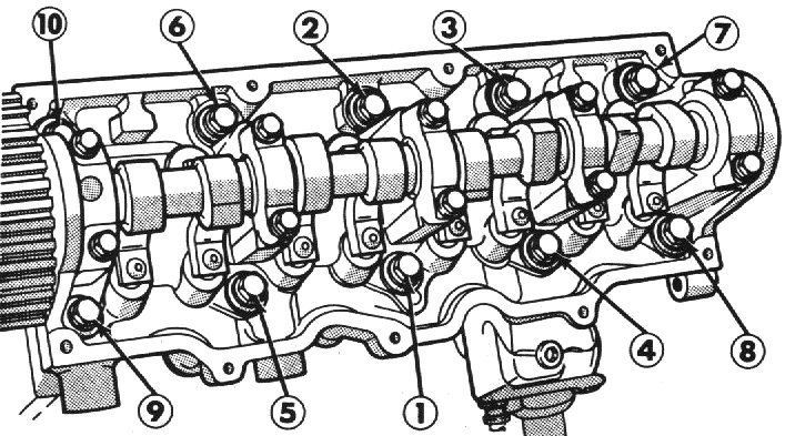
Head Bolt Tightening Sequence
Tighten the cylinder head bolts using the appropriate sequence shown below:
1985 and Earlier Engines (10mm head bolts)
First pass - All bolts to 35 ft-lbs (48 N-m)
Second pass - All bolts to 45 ft-lbs (61 N-m)
Third pass - All bolts again to 45 ft-lbs (61 N-m)
Forth pass - All bolts 1/4 turn (90 degrees)
1986 and Later Engines (11mm head bolts)
First pass - All bolts to 45 ft-lbs (61 N-m)
Second pass - All bolts to 65 ft-lbs (88 N-m)
Third pass - All bolts again to 65 ft-lbs (88 N-m)
Forth pass - All bolts 1/4 turn (90 degrees)

(click here for a larger image)
A/C Bracket Bolt Installation Sequence
Install the A/C bracket bolts in the sequence shown in the diagram so they are hand tight, then tighten them in this sequence:
First pass - Bolt #1 to 22 ft-lbs (30 N-m)
Second pass - Bolts #2 and #3 to 40 ft-lbs (54 N-m)
Third pass - Bolts #1, #4, and #5 to 40 ft-lbs (54 N-m)
Forth pass - Bolts #6 and #7 to 40 ft-lbs (54 N-m)
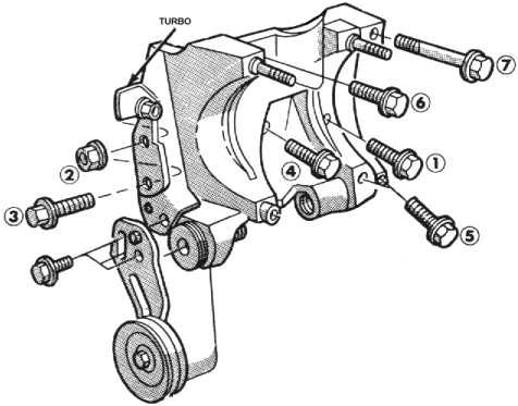
(click here for a printable image)
Updated 04/21/2004.
Copyright © 1996-2004 Russ W. Knize.