Left to right: old style (pre-'87) sensor with cable, new style 2-pin sensor with cable, new style 2-pin sensor without cable, 3-pin hall effect sensor
[ Upgrade To The 3-Wire Sensor | Convert Your 2-Wire Sensor ]
This page discusses possible upgrades for the speed/distance sensor for your vehicle from a mechanical switch to a hall effect sensor. There are two options available for those vehicles equipped with an electronic speedometer (analog or digital), but only one option for those who have a mechanical speedometer.
Left to right: old style (pre-'87) sensor with cable, new style 2-pin sensor with cable, new style 2-pin sensor without cable, 3-pin hall effect sensor
To figure out what you have, just look for a speedometer cable coming out of the speed/distance sensor. The sensor is usually located on top of the transmission housing extension for the right output shaft, though a few are located at the speedometer end of the speedometer cable. A mechanical speedometer system will have the speedometer cable coming off of the top of the sensor next to a two-wire cable. An electronic speedometer system will only have a 2 or 3 wire cable. If you have a 3 wire cable, then you already have a hall effect speed/distance sensor and can disregard this page.
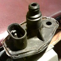
When replacing the old style (pre 1987) speed sensor with a new unit, you will receive the new style 2-pin version. In order to install it, you have to remove the old style sensor's base from the transmission housing by removing the 10mm bolt. It will also come with a short adapter cable.
So, if you have the 2-wire electronic speedometer, you can either upgrade to the 3-wire sensor or convert your existing 2-wire sensor. If you have a mechanical speedometer, then your only option is to convert your 2-wire sensor. See the Upgrade To The 3-Wire Sensor and Convert Your 2-Wire Sensor sections for more details.
This upgrade is only possible if you have an electronic speedometer in your vehicle. If you have one or plan to upgrade to one, then you have the option of using this method. On some vehicles, it is possible to upgrade your existing instrument cluster to a later version that uses an electronic unit, or to a digital unit. Look in your local salvage yards for candidate units. Here is a chart of all vehicles equipped with mechanical clusters and what can be used as an electronic replacement:
| Body | Upgrade |
| L | none |
| K, E | same year digital (tach or traveler) |
| H | same year digital or 1989 analog |
| P | 1990 - 1993 analog |
Some wiring changes will be required to make the change. You will need pin-outs of your vehicle and the donor vehicle. Also be sure to cut off the harnesses with the connectors you need for the new cluster. You can also try to install a digital cluster from another type of vehicle into yours. This would require more fabrication. As an example, to see how to install a 1987 Daytona/Lebaron digital instrument cluster into an L-body, see Jeff Barnett's Putting a Digital Dash in a GLH-S page.
If you are setup for the electronic system, the rest of the upgrade is easy. You will need a speed/distance sensor from any 1993 vehicle with a 2.2L, 2.5L or 3.0L engine. If you get one from a salvage yard, be sure to cut off the harness with the 3-wire connector. If you buy a new one, you will need to solder wires onto the pins of the sensor to be able to use it.
If you have the harness, skip this paragraph. Since you don't have the harness, you will have to solder wires right to the pins on the connector on the sensor. It's best if you use different color wires. You can also use a 3-pin connector, such as a trailer light harness connector set. If you don't know how to solder, you should try to find someone who can. If you can find some way to crimp the wires on so that they stay put, then go for it. Now you need to take note of what wire is for what. Holding the sensor with the top facing you and the connector at the bottom, the pins are from left to right: Power Input, Ground, and Signal Output. With the wires soldered in, fill the plug hole with RTV. This will protect the connection. Wick the RTV up past the lip of the connector hole around the wires to act as a strain relief.
Now you need to connect the harness you cut out or the wires and/or connector you bought to the vehicle. As above, holding the sensor with the top facing you and the connector at the bottom, the pins are from left to right: Power Input, Ground, and Signal Output. The power output needs to be connected to a 5V or 8V source. All vehicles except those equipped with a SBEC (1990 or later) have an 8V output from the power module or SMEC. See your wiring diagrams. If you do not have an 8V output, use the 5V supply that is used to power the TPS, etc. You can use an in line splicer, but it would be best if you soldered and tapes/shrink-wrapped the wires in. The ground needs to be the sensor signal ground. This is usually a black wire with a light blue stripe and it already provided by the original 2-wire cable. Just cut or splice into it. The same goes for the signal output. It is the other wire on the original 2-wire cable.
With the new sensor wired in, be sure to take the pinion gear off of the old sensor and put it on the new one and just install the new sensor. If you vehicle had a mechanical speedometer, be sure to either remove the speedometer cable or tape the end of it and tie-wrap it to something secure to keep it from hitting the exhaust manifold or turbo.
This method requires some fabrication, a good degree of electronics experience (basic electrical laws and ability to solder), and some patience. It basically consists of disassembling the old sensor, removing the mechanical switch inside, and installing an electronic hall effect sensor in its place. This will essentially make a 3-wire sensor out of it, therefore the installation procedure in the previous section applies.
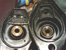
Modifying the early style sensor is definitely easier, since it has much more room inside (far left in the above picture). However there is still enough room inside the new style sensor to fit the necessary electronics. The magnet inside the sensor has 8 poles, 4 north and 4 south. The use of an omnipolar hall effect sensor (such as the Infineon TLE 4319, Digikey TLE4913INCT-ND) simplifies the circuit, since only one is needed. If a unipolar or bipolar sensor is used, then two will be required positioned 45 degrees from each other with respect to the poles on the magnet. This can be tricky, since the hysteresis of the sensors tends to make their outputs overlap if their range from the magnet is not perfect.
These pictures show a pair of unipolar hall effect sensors (Micronas HAL508UA-E) installed in a new style 2-pin speed/distance sensor. In addition to the sensor is a simple zener shunt power supply to keep the power clean.
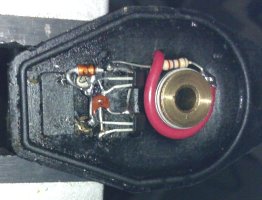
Note: a schematic will be available at some point. In the menatine, refer to the datasheet of the sensor you are using. Pay particular attention to the power supply requirements.
Once the circuit is completed and the connections double-checked, the position of the sensor(s) needs to be set. This is done by installing the shaft and magnet (make sure the spring washer is between the magnet and the shaft base), assembling the two halves, supplying power to the sensor and checking the output pin for continuity with the ground pin as the shaft is slowly rotated. The two should be shorted 8 times per shaft revolution. If they are not being shorted at all (check the circuit) or are shorted less than 8 times per rotation, bring the sensor closer to the magnet. If they are always shorted or become unshorted less than 8 times per rotation, move the sensor further away from the magnet. If two sensors are being used and the latter occurs or the pulses are not evenly spaced as the shaft is rotated, try moving the sensors closer or further apart from each other.
Once the circuit is tested, apply black RTV over the entire circuit and the power supply wire entry point being careful not to move the position of the sensor(s) and allow it to cure. Make sure that the RTV won't interfere with the two halves coming together. Once cured, retest the sensor as described above. For the final reassembly:
| Return to MiniMopar Resources |
Updated 05/27/2006.
Copyright © 1996-2006 Russ W. Knize.